- 积分
- 640
注册时间2008-8-18
参与分
技术分
精华
该用户从未签到
|
OK folks, there hasn’t been a grinder tutorial for sometime now,whenever I post one of mine up they get a lot of interest so thought Iwould show you how to make one of these
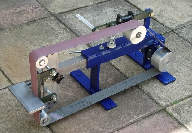
It’s basically a KMG clone uses 1600 to 2000 x 50 belts and the greatthing about these machines is there adaptability. It’s very simple tohave a platen grinding head, contact wheel or small wheel attachment
A general overview of the construction is, all welded main frame,sliding type tool arm lockable with a single fastener, single knobtracking system with variable spring tension, main drive pulley is100mm Dia x 55mm wide
Tracking pulley is 80 mm Dia ‘crowned’ x 55mm wide platen rollers 45mmDia x 50mm wide. This will be run with a 2hp motor and three speeddrive.
For those of you that have seen one of these in action you’ll know just how good they really are!!
As for the plan, their isn’t one, I’ve made quite a few of these nowand the major problem that I have is obtaining a regular supply ofsteel the sizes that I want, so I make them with the steel that’savailable to me,
The good news is that all the dimensions given are quite adaptable; aslong as you stick to very similar sizes you shouldn’t go wrong.
I will start of by making the main frame (the blue bit) first, It’s anall welded construction making for a very rigid frame, the disadvantageis you will need to be very careful in getting it clamped up square andspot on before you weld, as I’m sure you will appreciate it’s a realpain having to grind off welds when you get them wrong!
I intend to complete the grinder right through to fitting the motor and running it.
So here we go then let’s make a grinder
This is the steel that will be required to make the main frame and tracking arm, all materials are Bright mild steel
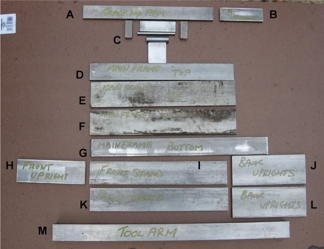
A = Tracking arm = 300 x 30 x 10mm
B = Tracking arm up-right = 100 x 30 x 10mm
C = Tracking hinge materials = (see separate bit on the tracking)
D = Main frame top section = 325 x 35 x 10mm (or use 1.5inch x 3/8inch)
E = Main frame side = 325 x 55 x 8mm (or 10mm )
F = Main frame side = 325 x 55 x 8mm
G = Main frame Bottom section = 390 x 35 x 10mm
H = Front up-right = 150 x 50 x 10mm
I = Front stand = 300 x 50 x 10
J = Rear up-right/bearing carrier = 150 x 65 x 10mm
K = Rear stand = 300 x 50 x 10mm
L = Rear up-right/bearing carrier = 150 x 65 x 10mm
M = Main tooling arm = 500 x 35 x 35 mm
Here is there corresponding position on the frame

Now before we get the MIG out we need to drill a few holes
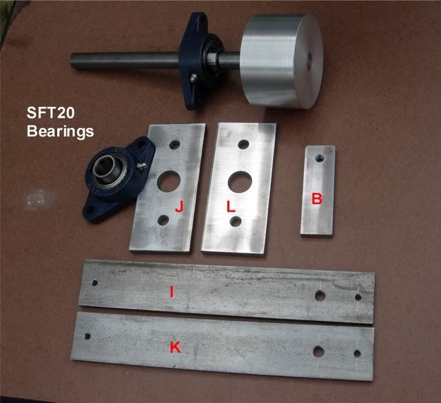
I will be using SFT20 bearing for the main drive pulley, so we have todrill the up-rights (items J and L 150x65x10) measure down from thetop, 25mm (this is where the first 11.5mm hole goes), mark the centreline, and drill to suit the bearings, make the main mounting holes11.5mm and the centre hole 25mm that way it allows for a bit ofadjustment.
The tracking arm up-right (item B 100x30x10) mark the centre and measure down 15mm from the top drill (8.5mm) and tap M10
The two stands (items I and K 300x50x10) mark the centre line measurein 15mm from each end drill 6mm from one end only measure in 50mm anddrill 10mm (this is for the motor mounting frame, not shown yet)
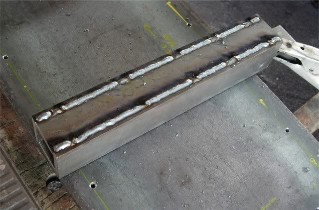
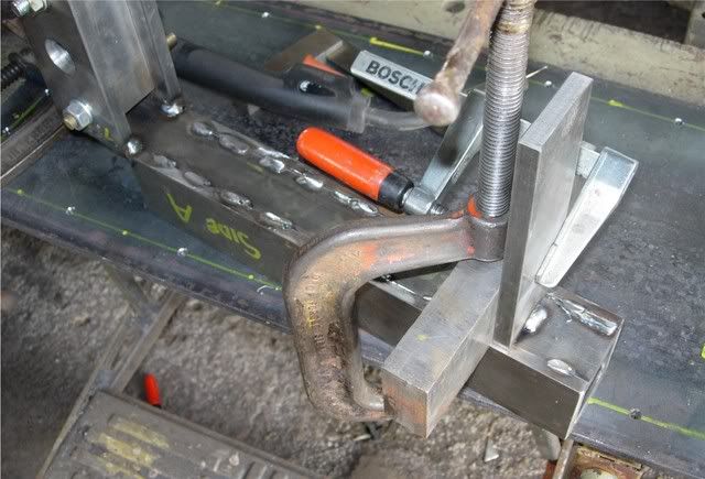
Right now with that successfully done we move onto the next bit, thisis where we get serious, we now have to make a box around the main toolarm, to make this as easy as possible we will use the tool arm as a jig,
You will need several clamps and bits of metal to get this right, placethe top and bottom box sections opposite each other on the tool arm, wewill need a bit of clearance here so insert a couple of thin (1mm) bitsof steel between the tool arm and bottom section clamp into place, fitthe sides, position so the top is level and clamp into place, youshould have the lower section with 65mm protruding out from the back (G on the third picture down)
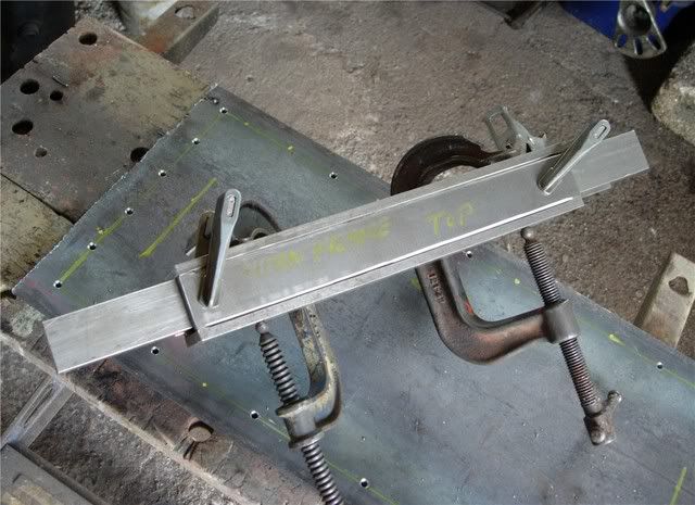
When happy with your clamping, tack weld in several places, removeclamps check for square and alignment and that the tool arm slides inand out easily if your happy with it weld it up, then grind and cleanup the welds on the top section,
Now we will fit the rear up-rights (item J and L) when I make these Ialways drill as a pair, when it comes to welding them into place theyneed to be spaced at 38mm apart on the inside edge this is to allow oneof the drive bearings to fit between the up-rights, this is best donewith a block of metal (I use an off-cut from the tooling arm @35mm plus3x 1mm shims making 38mm)
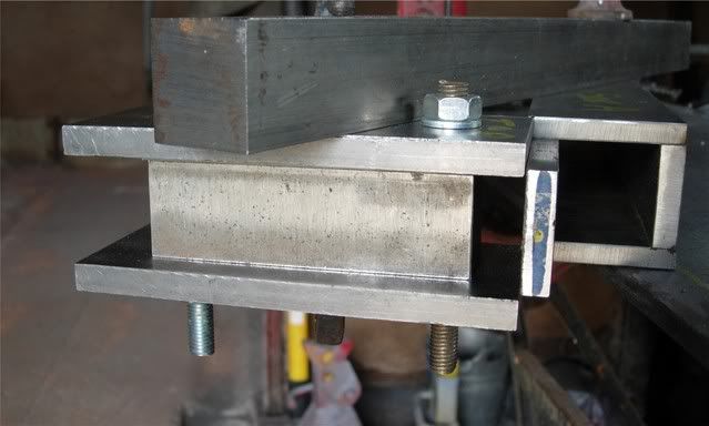
Position the up-rights as in the photo (above)and use the tool arm tomake sure they are in line with side A (this is the side the tool armclamps against so everything must be aligned with this side) use asquare to get them exactly up-right when you are happy with theposition weld into place, (do not remove the spacer block) should looklike this if you got it right
Next is the front up-right (item H 150x50x10) using a block position35mm back from the front of the grinder, make sure its square and weldinto place
If we are doing ok you should have something like this
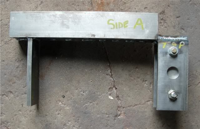
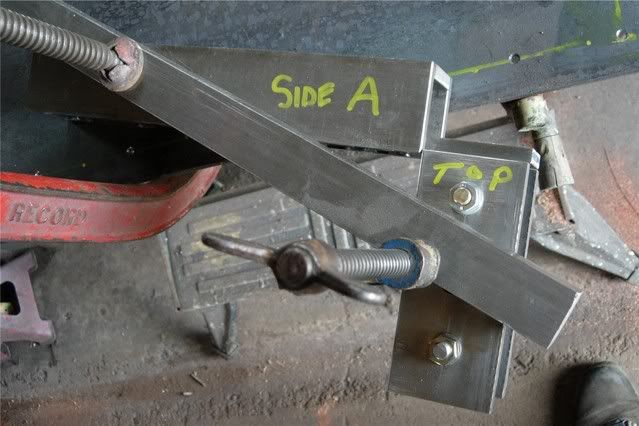
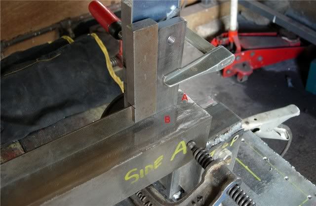
Now its time for the stands (items I and K 300x50x10) measure in 100mmfrom the end (distance A in picture below) use metal block and squareto get it right when happy weld into place, now do the same with thefront stand making sure that the two 10mm holes are on the oppositeside to side A
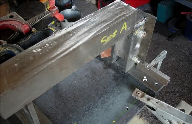
The final bit of welding on the main frame is the tracking arm up-right
(item B 100x30x10) position A = 15mm in and B = 35mm in make sure its square and weld into position
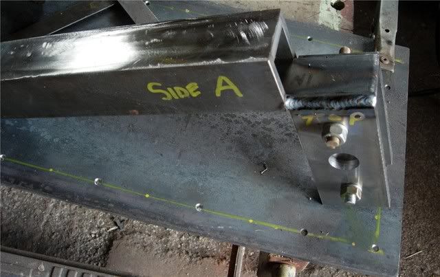
If progress is going to plan you should have something like this

That’s it for now folks next instalment is the tracking arm, tracking hinge and tracking pulley
Thanks Aly |
|


 发表于 2010-1-21 00:04

 楼主
楼主


